


Low Voltage VFDs
- Commodity name: Low Voltage VFDs
- Description
- Product Features
- Product Selection
- Product Mix
- Public Technical Specifications
- Industry Applications
-
The NS6000 series frequency converter is a low-voltage classic product carefully polished by Lipu Company for decades. The hardware uses branded power devices, capacitors, etc., and the software uses extremely high-performance vector control technology. With a process flow of more than ten years of tempering, the 6000 series frequency converter has high reliability, excellent dynamic characteristics, and strong overload capacity. The 6000 series integrates complete hardware configuration and software functions, with stable performance and rich and powerful functions. It is widely used as a driver for textile, papermaking, air compressors, wire drawing, machine tools, packaging, food, fans, water pumps, and various automated production equipment
-
Model
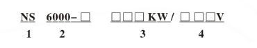
Jiangsu Lipu Electronic Technology Co., Ltd. - Low voltage frequency converter series name code
Product type: 6000-1 universal, mechanical industry, fan and water pump, 6000-2 air compressor specialized type, mainly in the air compressor industry;
Machine power capacity;
Voltage level: 220V, 380V, 690V (customizable according to user needs)
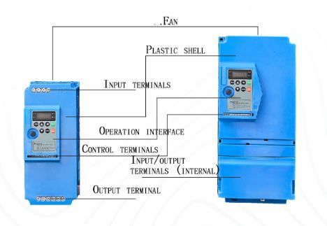
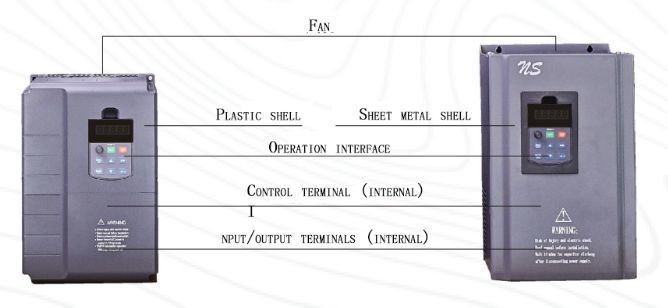
System composition
Technical characteristics
☆SVC open-loop vector control, FVC closed-loop vector control (limited to 6000-1-3), V/F control (6000-1-3)
☆Strong overload capacity, 150% rated current/60s, 180% rated current/3s
☆Superior performance and good environmental adaptability
☆Simple structure, suitable volume, and easy installation
☆High performance vector frequency converter with high torque output can ensure smooth motor startup during heavy loads ☆It has the function of instant stop and fast current limiting, which can reduce the probability of frequent fault alarms in the frequency converter
☆Complete protection functions, including output phase loss protection, overcurrent/overvoltage overload/overheating protection, and other functions
☆Suitable for various scenarios such as textile, papermaking, wire drawing, machine tools, packaging, food, fans, water pumps, air compressors, and various automated production equipment ☆Support permanent magnet synchronous motor control (limited to 6000-2 series) ☆Power range: 380V: 0.75-450kw
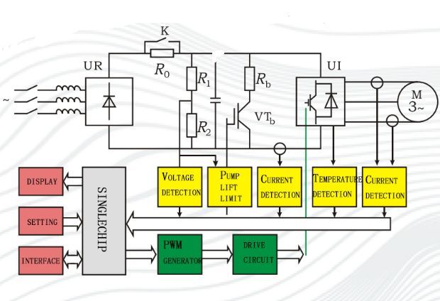
Topology diagram
-
NS6000 Series Product Selection Table
NS6000 Series Product Selection Table Frequency Converter Mode Rated Output Power KW Rated Output Current A Adapted Motor (KW) NS6000-1-0.75KW/380V 0.75 2.1 0.75 NS6000-1-1.5KW/380V 1.5 3.8 1.5 NS6000-1-2.2KW/380V 2.2 5.1 2.2 NS6000-1-3.7KW/380V 3.7 9 3.7 NS6000-1-5.5KW/380V 5.5 13 5.5 NS6000-1-7.5KW/380V 7.5 17 7.5 NS6000-1-11KW/380V 11 25 11 NS6000-1-15KW/380V 15 32 15 NS6000-1-18.5KW/380V 18.5 37 18.5 NS6000-1-22KW/380V 22 45 22 NS6000-1-30KW/380V 30 60 30 NS6000-1-37KW/380V 37 75 37 NS6000-1-45KW/380V 45 90 45 NS6000-1-55KW/380V 55 110 55 NS6000-1-75KW/380V 75 152 75 NS6000-1-93KW/380V 93 176 93 NS6000-1-110KW/380V 110 210 110 NS6000-1-132KW/380V 132 253 132 NS6000-1-160KW/380V 160 304 160 NS6000-1-185KW/380V 185 340 185 NS6000-1-200KW/380V 200 380 200 NS6000-1-220KW/380V 220 426 220 NS6000-1-250KW/380V 250 465 250 NS6000-1-280KW/380V 280 520 280 NS6000-1-315KW/380V 315 585 315 NS6000-1-350KW/380V 350 650 350 NS6000-1-400KW/380V 400 725 400 NS6000-1-450KW/380V 450 820 450 Frequency Converter Mode Rated Output Power KW Rated Output Current A Adapted Motor (KW) NS6000-2-0.75KW/380V 0.75 2.1 0.75 NS6000-2-1.5KW/380V 1.5 3.8 1.5 NS6000-2-2.2KW/380V 2.2 5.1 2.2 NS6000-2-3.7KW/380V 3.7 9 3.7 NS6000-2-5.5KW/380V 5.5 13 5.5 NS6000-2-7.5KW/380V 7.5 17 7.5 NS6000-2-11KW/380V 11 25 11/15 NS6000-2-15KW/380V 15 32 15/18.5 NS6000-2-18.5KW/380V 18.5 37 18.5/22 NS6000-2-22KW/380V 22 45 22/30 NS6000-2-30KW/380V 30 60 30/37 NS6000-2-37KW/380V 37 75 37/45 NS6000-2-45KW/380V 45 90 45/55 NS6000-2-55KW/380V 55 110 55/75 NS6000-2-75KW/380V 75 152 75/93 NS6000-2-93KW/380V 93 176 93/132 NS6000-2-110KW/380V 110 210 110/132 NS6000-2-132KW/380V 132 253 132/160 NS6000-2-160KW/380V 160 304 160/200 *When placing an order, please inform our company of the product model, specifications, load conditions, and usage conditions in order to select the corresponding product.
*For users who have special functional requirements or special usage conditions for the product, please inform our company when placing an order, and we will provide comprehensive services. -
6000-1 Series

6000-1 Size Table (Installation Dimensions And External Dimensions)
Power (KW) A(mm) B(mm) H(mm) W(mm) D(mm) Installation Aperture (mm) Structure Installation Dimensions External Dimensions 1.5-2.2 106 175 185 118 153 4 Plastic Shell 3.7-7.5 148 235 247 160 175 5 11-15 205 305 320 220 197 6 18.5-22 160 369 382 230 186 6 Metal Wall Nounted 30-37 200 466 486 253 247 7 45-55 240 533 551 370 300 9 75-110 300 650 670 400 310 11 132-160 400 800 820+400E 500 320 11 Metal Wall Mounted And Cabinet Type 185-220 450 870 900+500E 550 380 13 250-315 514 1000 1030+500E 614 380 13 350-450 600 1180 1210+500E 650 450 13 *When placing an order, please inform our company of the product model, specifications, load conditions, and usage conditions in order to select the corresponding product.
*For users who have special functional requirements or special usage conditions for the product, please explain to our company when placing an order, and we will provide comprehensive services
6000-2 series
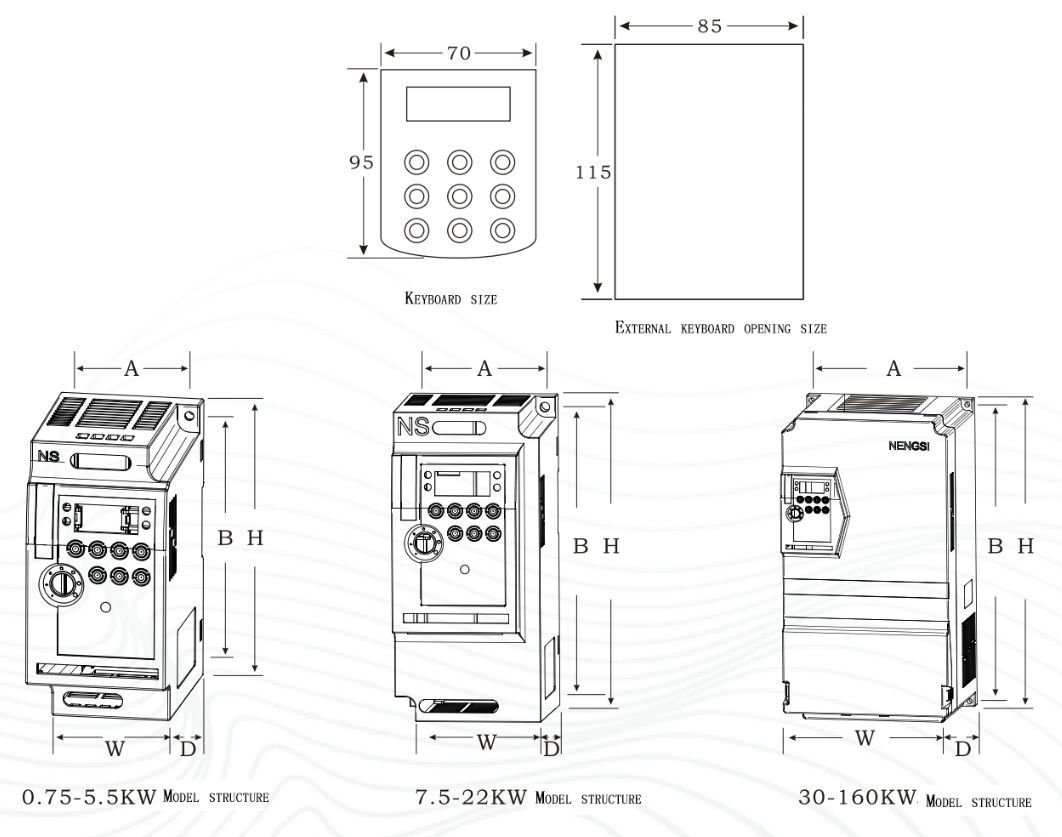
6000-2 SIZE TABLE (INSTALLATION DIMENSIONS AND EXTERNAL DIMENSIONS)
Power (KW) A(mm) B(mm) H(mm) W(mm) D(mm) Installation Aperture (mm) Structure Installation Dimensions External Dimensions 0.75-2.2 61.6 130.5 141.05 71.18 105.5 4.5 Plastic Shell 3.7-5.5 72.8 167.4 179.01 84.41 109.8 5.5 7.5-11 95.9 230.8 240.63 105.17 142.2 4 15-22 136.8 317.1 332.4 150.52 161 7.2 30-37 203.5 386.6 400.02 217.02 193.5 6.3 45-55 240 533 551 370 300 9 Metal Wall Nounted 75-110 300 650 670 400 310 11 132-160 400 800 820+E 500 320 11 *When placing an order, please inform our company of the product model, specifications, load conditions, and usage conditions in order to select the corresponding product.
*For users who have special functional requirements or special usage conditions for the product, please explain to our company when placing an order, and we will provide comprehensive services
-
Product Series Project
6000-1/6000-3
6000-2 Power Range
0.75KW~450KW
0.75KW~160KW Input
Rated Voltage
3PH 380V±15%
3PH 380V±15% Rated Frequency
50/60Hz±10%
50/60Hz±10% Output
Voltage
380V 0~380V
380V 0~380V Frequency
Vector control: 0-300Hz
V/F control:0~3200Hz0~600Hz Overload Capacity
G-type machine: 150% rated current for 60 seconds; 180% rated current for 3 seconds.
P-type machine: 120% rated current for 60 seconds; 150% rated current for 3 seconds.150% rated current for 60 seconds; 180% rated current for 3 seconds. Starting Torque
G-type machine: 0.5Hz/150% (SVC) 0Hz/180% (FVC);
P-type machine:0.5HZ/100%0.5HZ/150% Control Mode
Open Loop Vector (SVC) Closed Loop Vector (FVC) V/F Control
Open loop vector control (SVC) Display
4-digit digital tube display/5-digit digital tube display
5-digit digital tube display Control Characteristics
Carrier Frequency
0.5kHz~16kHz can automatically adjust the carrier frequency according to the load characteristics.
Frequency Setting Resolution
Digital setting: 0.01Hz Analog setting: Maximum frequency * 0.025%
Output Frequency accuracy
0.1Hz
Speed Regulation Range
1:100(SVC) 1:1000(FVC)
1:200 Stable Speed Accuracy
±0.5%(SVC) ±0.02%(FVC)
+0.5%(SVC` Acceleration And Deceleration Time
0.00S~ 65000.0s
Torque increase
Automatic torque increase; Manual torque increase0 . 1%~30 . 0%
/ Torque Control accuracy
±5%(FVC)
/ V/F Curve
Three methods: suitable for line type; Multi point type; Nth power V/F curve
/ V/F separation
Two methods: full separation and semi separation
/ Acceleration and deceleration Curve
Linear or S-curve acceleration and deceleration methods. Four types of acceleration and deceleration times
Linear acceleration and deceleration, S-curve acceleration and deceleration A, S-curve acceleration and deceleration Jog Contro
Jogging frequency range: 0.00Hz~50.00H: Jogging acceleration and deceleration time: 0.0s~65000s
Braking Mode
DC braking frequency: 0.00Hz~high frequency
Moving time: 0.0s~36.0s
Braking action current value: 0.0%~100.0%Immediate DC braking, deceleration DC braking, low-frequency braking Simple PLC
Multi Speed OperationUp to 16 segments of speed operation can be achieved through built-in PLC or control terminals
Other Configurations
PID Control
Built in PID control
Multifunctional Input Terminals
Multiple options for analog input, forward and reverse rotation, etc
Multifunctional Output Terminals
Specific signal outputs such as faults
Braking Circuit
Brake unit
Configurable Communication
Standard Rs485 communication function (MODBUS)
Protection Function
Overload Protection
Standard configuration can be set downwards
Standard configuration can be set downwards Overvoltage Protection
Can be set
Can be set Undervoltage Protection
Can be set
Can be set Other Protections
Phase loss, overheating, short circuit, overcurrent, abnormal current detection, parameter locking, etc
Environmental Characteristics
Place Of Use
Indoor, not exposed to sunlight, without dust, corrosive gases, flammable gases, oil mist, water vapor, dripping water or salt, etc
Ambient Temperature
10 ℃~+40 ℃ (ambient temperature between 40 ℃~50 ℃, please reduce the rating for use)
Storage Temperature
20℃~+60℃
Environmental Humidity
Below 95% (without condensation)
Altitude
Below 95% (without condensation)
Vibration
Cooling Method
Forced air cooling
Protection Level
IP20
Installation Method
Wall mounted
Size
See dimension table

LP6000-1Control Terminals Category
Terminal Symbols
Terminal Name
Function Description
Source
+10V-GND
External+10V power supply
Provide+10V power supply to the outside, maximum output current: 10mA
Generally used as an external potentiometer working power supply, the resistance range of the potentiometer is 1k2~5k2+24V-COM
External+24V power supply
Provide+24V power supply externally, generally used as a working power supply for digital input and output terminals and external sensor power supply
Source. Maximum output current: 200mAOP
Internal 24V power supply
When using an internal 24V power supply, it is necessary to short circuit the OP terminal and the+24 external terminal. Use 24V for control
When supplying power to the board, it is necessary to remove the short connectors from the OP terminal and the+24V terminal.Analog Input
AI1-GND
Analog Input Terminal 1
1. Input voltage range: DC 0V~10V
2. Input impedance: 22k ΩAI2-GND
Analog Input Terminal 2
Input range: DC OV~10V/0mA~20mA, determined by the J8 jumper selection on the control board.
Input impedance: 22k2 for voltage input and 5002 for current inputDigital Input
X1-OP
Digital Input 1
Optical lotus isolation, compatible with bipolar
Input impedance: 2.4k Ω
Voltage range during level input: 9V~30VX2-OP
Digital Input 2
X3-OP
Digital Input 3
X4-OP
Digital Input 4
X5-OP
High Speed Pulse Input Terminal
In addition to the characteristics of X1~X4, it can also be used as a high-speed pulse input channel.
Maximum input frequency: 100kHzAnalog Output
AO1-GND
Analog Output 1
From J4 on the control board The selection of J5 jumper determines the voltage or current output.
Output voltage range: OV~10V Output current range: 0mA~20mAAO2-GND
Analog Output 2
FM-CME
High speed pulse output
Constrained by function code F5-00 "FM terminal output mode selection", when used as high-speed pulse output, the highest
Frequency up to 100kHz; When used as a collector open circuit output, the specifications are the same as DO1.Relay Output
TA-TB
TA1-TB1Normally closed terminal
Contact driving capability: AC250V, 3A, COSφ=0.4
DC 30V.1ATA-TC
TA1-TC1Normally open terminal
485 Communication port
485+
485-
485 signal+terminal
Position Xi485 communication terminal
J3
PG Card Interface
Optional: OC, Differential, UVW, Rotary transformer and other interfaces

LP6000-2-3 control terminal Category
Terminal symbols
Terminal Name
Function Description
Source
+10V-GND
External+10V Power Supply
Provide+10V to the outside,with a maximum output current of 10mA
Analog Input
AV1-GND
Analog Input Terminal
Imput voltage range:0-10V (input impedance:22KQ)
Input current range:0-20mA (input impedance:5002)Digital Input
REV-GND
(REW It is effective when short
circuiting between FWD,S1,S2,S3,
S4)and GND,and its functions are set
by parameters P4.00~F4.39
respectivek1.Optical lotus isolation,compatible with bipolar input
2.Imput impedance.2.4k 2
3.Voltage range during level input:9V~30VFWD-GND
S1-GND
S2-GNDS3-GND
(Public end:GND)。
S4-GND
Relay Output
RA-RB
Normally Closed Terminal
Contact driving capability:AC250V,3A,COSφ=0.4 DC 30V,1A
RA-RC
Normally Open terminal
485
Communication
portRS+
RS485 Signal+terminal
Standard RS485 communication interface,not isolated from GND
Please use twisted pair or shielded wireRS- RS485 Signal-terminal *When placing an order, please inform our company of the product model, specifications, load conditions, and usage conditions in order to select the corresponding product.
*For users who have special functional requirements or special usage conditions for the product, please explain to our company when placing an order, and we will provide comprehensive services
-
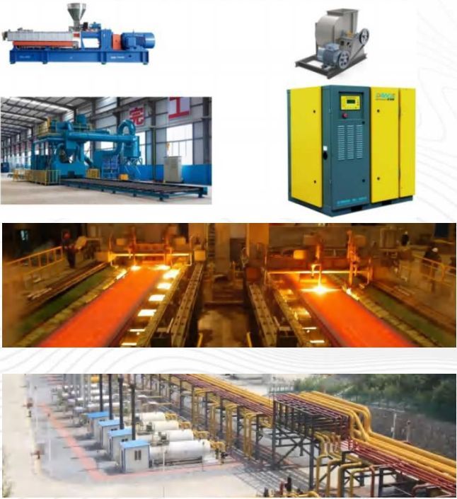
Low voltage frequency converters are widely used in various industries, such as metallurgy, chemical industry, papermaking, machinery, etc. The specific application is more extensive, with small-scale applications such as blowers, conveyors, feeders, mixers, grinders, crushers, paper cutters, rolling mills, extruder valves, compressors, cooling towers, plastic machinery, elevators, and various textile machinery in various industries. Large application areas include paper mills in paper mills, injection molding machines in mold factories, steel mills in metallurgical plants, as well as large fans, water pumps, cranes, and oil pipelines in chemical and other industries. The use of a frequency converter to form a variable frequency speed control transmission system has achieved or exceeded the performance of a DC speed control system. The frequency converter has the advantages of small size, low noise, and can also use low-cost and easy to maintain asynchronous motors, greatly simplifying the process and reducing initial investment costs. Overall, the use of frequency converters can meet the requirements of improving labor productivity, product quality, equipment automation, quality of life, and living environment. It can also save energy and reduce production costs for enterprises.
Key words:
High And Low Voltage Frequency Conversion | Soft Starter Introduction | Power Quality Management | New Energy
Get A Quote
-
File size: 1004.9KB
Get A Quote
Note: Please leave your email address, our professionals will contact you as soon as possible!


力普
Tel:
Sales E-mail: